
Tesla Model Y Heat Pump Details Infrequently Discussed By The Media
The addition of the heat pump, the liquid-cooled condenser loop, and the 8-way octovalve opens up many ways of moving heat.


Tesla’s new system “boosts” the heat pump to give it better efficiency than regular heat pump systems and uses some unique methods for heating below -10 degrees C.
There’s been a lot written about the Model Y climate control system. The “go-to” talking points are the new heat pump and the octovalve, but there’s way more to this system. We’ll discuss some of the finer points of the system in this article.
If you have an appreciation for thermodynamics you will love this description of Tesla’s new system:
“The system conducts thermodynamic arbitrage from finite source thermodynamic sources and has the ability to augment those finite sources “
Most of the interesting points concern heating mode but before we get into that, let’s first quickly discuss cooling mode.
Cooling Mode
For the most part cooling mode is fairly similar to Model S and Model 3, with one exception. Tesla has now added a “liquid-cooled condenser” to the system. The condenser is where the hot liquid refrigerant rejects its heat. In Model S and Model 3 the air conditioning condenser is in the front of the car. Refrigerant lines (not glycol lines) run all the way to the front of the car and back.
The space up front is shared with a glycol heat exchanger so there are 2 heat exchangers up front in Model 3. They are stacked one in front of the other. In Model Y the air conditioning condenser is on the firewall of the car and a coolant loop carries glycol to the front of the car to dump the heat. The beauty of this approach is that there is now only ONE heat exchanger up front, not 2 (or 3 in the case of Model S).

Model Y uses a liquid-cooled condenser

Model Y only has 1 heat exchanger in the front of the car
Heating mode
Many ways to move heat
The interesting details not frequently discussed center around the additional ways this system can move heat between the passenger cabin, the battery, the drive unit and outside ambient to improve system efficiency beyond that of just a plain heat pump. Many of the heat sources are low-grade energy sources and they need to be augmented at a temperature below -10C (14F). The patent describes a number of ways Tesla can do this without using a high voltage heater.
The system has continually improved between Model S, Model 3 and Model Y. Model S had the capability to heat the battery with waste heat from the drive motor and inverter but that was about the extent of its flexibility. The rest of the system used a sledgehammer approach to heating with an “in-cabin” high voltage heater (no glycol loop) and a conventional air conditioner with refrigerant (not glycol) pumped all the way to the front of the car to be cooled. Model S and Model 3 had a 4-way valve that offered a little flexibility to the system but in Model S, all the components were strung about under the cavernous frunk.

Photo showing clumsy layout of model S TMS

Model S only had one way of moving waste heat
Model 3 operated in much the same way as Model S except Tesla introduced “Mr. Super Bottle”. The big thing about super bottle is that it brought all the components into one location (the bottle) instead of spreading them about and connecting them with tubes and wires.

In Model 3 Tesla consolidated all the TMS components on “Mr. Super Bottle”
Model Y is a quantum jump
The addition of the heat pump, the liquid-cooled condenser loop, and the 8-way octovalve opens up many ways of moving heat. The patent actually discusses a total of 12 heating modes and 3 cooling modes. The system even uses the thermal mass of the battery to store heat. Then, the battery can be used as a heat source as we draw down the thermal energy stored in the pack.
We will show you two of the most interesting modes that this system can be configured. If you want a detailed description of all the modes, see the last section in this article and also the Tesla patent: US 2019/0070924A1, Optimal source electric vehicle heat pump with extreme temperature heating capacity preconditioning, March 7, 2019.
The single best mode of the heating system is shown in the figure below.

Model Y can heat the cabin with 3 sources of heat- mode 9
In mode 9 the system is using 3 sources to heat the cabin: ambient heat drawn from the front radiator (same as a conventional heat pump), the battery, and the drive motor and inverter. Using the higher temperature battery and drive motor heat sources improves the efficiency of the system because heat pumps work best at warmer ambients. This is very similar to how a residential geothermal heat pump works where the heat pump pulls heat out of the ground in the winter.
Figure 7 below shows another interesting mode where we draw heat from the passenger cabin to warm the battery. This mode could happen on a sunny winter day when the car is parked. The cabin is heated up from the sun but the battery is cold. In this case, we use solar energy to heat the battery. Heat is stored in the battery for later use to heat the cabin. Tesla is using the thermal mass of the battery to store heat. When they pull it back out they allow the pack temperature to drop to 10C (50F). The amount of heat energy that could be stored in the pack calculates out around 2.5-3 kWh so the battery can hold a decent amount of heat.

On a sunny winter day Model Y could heat the battery using the solar heat stored in the cabin
These two examples above show you the flexibility this new system allows in moving heat among many components and in many directions.
Heating at ambient temps below -10C (14F)
The other way Tesla’s new system shines is in the creative ways it can heat at cold ambients below -10C. These techniques (with the exception of 12V aux heating) are also used in commercial heating systems but have never been applied to an EV thermal management system (with the exception of Kia/Hyundai systems, which come close to duplicating Model Y tricks).
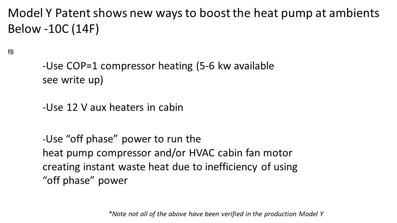
Model Y methods of heating at ambients below -10C (14F)
There are three methods Tesla outlined in the patent for heating below -10C. The primary one is COP=1 compressor heating.

In COP=1 compressor heating, we run the cabin evaporator and cabin condenser at the same time and recirculate cabin condenser discharge air back into the evaporator inlet.
In this mode, we run the cabin evaporator and cabin condenser at the same time and recirculate cabin condenser discharge air back into the cabin evaporator inlet. This is a bit like running your refrigerator with the door open (see the beginning of part 1 video in the detailed discussion section).
In this case, the heat absorbed in the evaporator is canceled out by the heat discharged in the cabin condenser and the net heat input to the cabin is equal to the electrical input to the compressor. This is an admittedly obscure way of doing things to us laymen but it is used in large commercial HVAC systems. Compressor electrical input to 3-4 ton compressors, such as Model Y’s can be in the neighborhood of 5-6 kW, so that’s on par with existing EV “in-cabin” resistive heaters. It is a decent amount of heat.
In the second method, we use 12V auxiliary heaters in the cabin as a heat supplement.
In the third method, we make “off-phase” electrical current in the inverter. We then use this “off-phase” power to run the compressor and blower motor to create more heat.
Unfortunately, these 3 methods only offer COP=1 heating so (in most cases) the closer we get to -10C the more our COP approaches 1.
More Tesla Analysis:
Unanswered questions
Most of what we have shown you based on the patent. Some of the things in the patent are verified in Sandy Munro’s Model Y teardown videos like having both an evaporator and a condenser in the cabin loop. However, some are not. For example, Sandy never showed us the 12V heaters or the COP=1 compressor heating mode. Also, we don’t know if Tesla has gotten rid of Model 3’s “locked drive motor and current through the windings” trick that it used in Model 3.
We are speculating that the “locked rotor current thru winding trick” in Model 3 has gone away and that Tesla is using COP=1 compressor heating and 1000 watt, 12V aux heaters for additional heat at cold ambients as in the patent.
Detailed description of all 15 modes.
Modes 1 -12 are heating mode. There are 3 air conditioning modes (modes 13-15).
We will give you a simple word description here. You can see a more detailed description of each mode in “Untangle Club” 3 part YouTube video series titled “Octovalve heat pump and thermal management system- working in detail” parts 1-3 in which they show you an animated drawing of all the components in the system, how the glycol and refrigerant move, how the heat moves and the position of the octovalve for each mode.
Up front, in part 1, they show you how the octovalve works. It is just two 4-way valves stacked on top of each other with a stepper motor to rotate the central disk. The modes are divided up into 2 temperature ranges: above -10 deg C (14F) and below -10C. The system COP begins to decrease below -10C as we add more COP=1 compressor heating.
COP=1 compressor heating is another new feature in Tesla’s system. It is used to replace the high voltage cabin heater that Tesla used in all previous models. COP=1 compressor heating is used in larger commercial refrigeration systems but to our knowledge has not been used before in an EV HVAC system (except perhaps Kia/ Hyundai). Its operation was described in figure 9 in the previous section.
We've embedded the videos below, along with timestamp breakdowns with descriptions:

Mode 1, heating, video part 1 @6:29. ambients above -10C (14F). Radiator heat heats cabin. Drive unit heats battery.
Mode 2, heating, video part 1 @7:53, ambients less than -10C (14F). Drive unit and battery heat cabin. Limited heat available in this mode so only used to maintain temp.
Mode 3, heating, video part 2 @ 0:55, ambient less than -10C. Cabin is cold. 12V heaters are added and like mode 2 battery and drive train heat cabin.
Mode 4, heating, video part 2 @ 1:37, ambient less than -10C. Battery doesn’t have enough heat to heat the cabin so COP=1 compressor heat is added. Total heat put into cabin from compressor is equal to the electrical energy put into the compressor (estimated 5-6 kw available so comparable to a resistance cabin heater)
Mode 5, heating, video part 2 @ 3:15, ambient less than -10C. Cabin and battery need heating. Like mode 4 the compressor @ COP=1 supplies heat = to its electrical input. If drive unit is hot enough it can heat the battery.
Mode 6, heating, video part 2 @ 4:08, ambient less than 10C. Only battery needs heat. As in mode 4, compressor provides heat @ COP=1.
Mode 7, heating, video part 2@10:06. Cabin is not being used but is warm. Example sunny winter day sitting in parking lot. Cabin heat is used to warm battery. Heat in battery is then used later for cabin heating when required.
Mode 8, heating, video part 2 @ 6:53. Same as mode 7 only after a drive and cabin is warm from the drive.
Mode 9, heating, video part 2 @ 7:37, ambient above -10C. Battery drive unit and radiator all used to heat cabin
Mode 10, heating, video part 2 @ 8:34. Defogging, cold air to glass, hot air to cabin
Mode 11, heating, video part 3 @ 0:27. Frost removal using heat stored in battery
Mode 12, heating, video part 3 @ 1:32. De humidify and reheating. Evaporator removes humidity and condenser heats cabin. Excess heat of drive unit and compressor released to atmosphere thru radiator.
Mode 13, Cooling, video part 3 @ 2:24, used during super charging. Battery needs cooling and cabin needs heating
Mode 14, cooling, video part 3 @ 3:25. Battery and drive unit both need cooling, cabin needs heat. Heat dumped to radiator
Mode 15, cooling, video part 3 @ 4:34. Battery, Drive unit and cabin need cooling. Heat is dumped to ambient in radiator.
*Credit:
Keith Ritter PE
Engineered Compliance
Energy Analysis
engineeredcompliance@gmail.com
RECOMMENDED FOR YOU

A Tesla Model Y Battery Test Looked Bad. Then The Degradation Almost Stopped
Polestar EVs Are A Whopping $25,000 Off After The Brand Got Kicked Out Of America
The Rivian R2 Is Just As Efficient As A Tesla Model Y, Despite Weighing More
This Is Tesla's New, Bigger Model Y For The U.S.
This Low-Mileage 2025 Tesla Model Y Lost A Lot Of Range Fast
BYD Reclaimed The EV Sales Crown Despite Tesla's Huge Quarter
Tesla Model Y Battery Tested After 16,000 Miles Of Mostly Fast Charging